After building the battery monitors and discovering that one of my batteries was essentially dead, I wanted to quantify just how dead it was. The best way appears to be adding a resistive type load of known amperage and calculating battery capacity with those numbers.
Starting off: a junction box, some H4 bulb holders and some headlight bulbs:
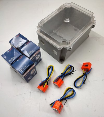
The box was around Rs 400 on Amazon and the bulb holders were Rs 80 each, bulbs were about the same.
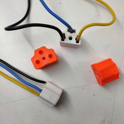
I removed the rubber sleeve, drilled a 4.5mm hole from the rear side, put back the rubber sleeve on, and continued drilling from the socket side and ended up with a clean hole in the rubber sleeve this way.
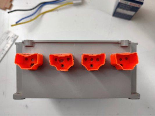
Spacing out the holder and marking holes for drilling.
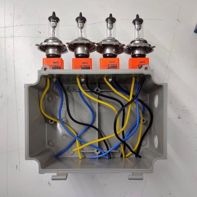
Holders installed.
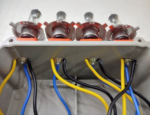
Each wire got an individual hole and the fasteners are M4 with serrated nuts.
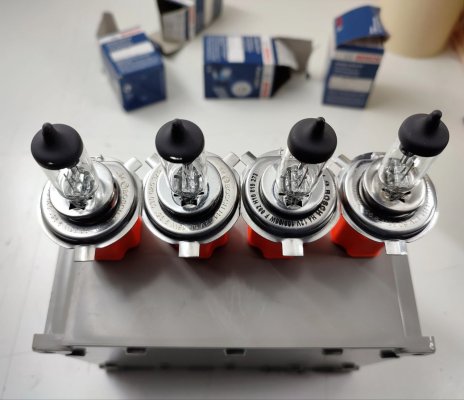
There is some crowding on the bulb side though, I should've staggered the holders a bit.
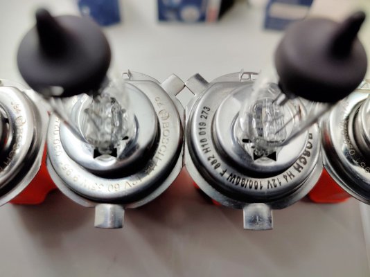
I needed to snip off bits from the bulbs to get them fit.
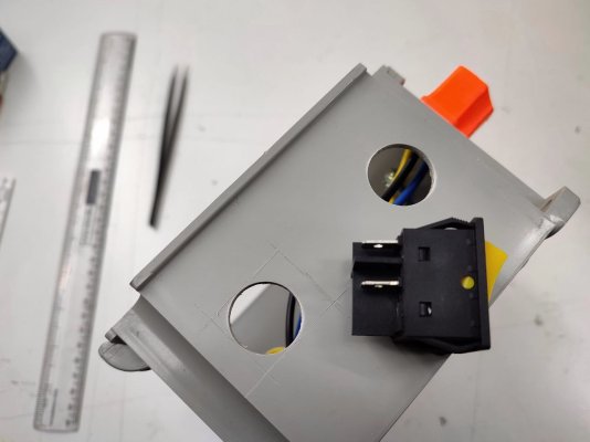
Next up is installing this rectangle switch in a round hole.
Link for the 30A switch: https://www.amazon.in/FIREWELD-Rocker-Welding-Machine-machines/dp/B08QZVM5D6
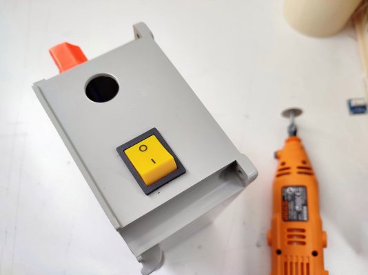
Which was done with the help of a rotary tool.
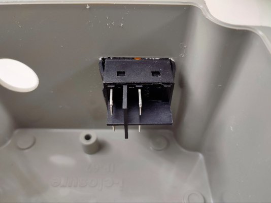
I wasn't able to clean up the hole because the switch got stuck during a test fitting. It looks alright though.
At this point, that's the most essential parts of the load tester. But I wanted some telemetry, so onwards we go.
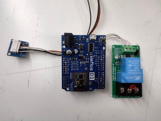
That's a Wemos D1 R2 ESP8266 module running Tasmota Sensors, connected to an INA219 for voltage monitoring and a 30A relay that serves as a low voltage cut off.
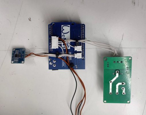
The wiring is the same as the battery monitors, with the addition of 5V lines and GPIO12 going to the relay.
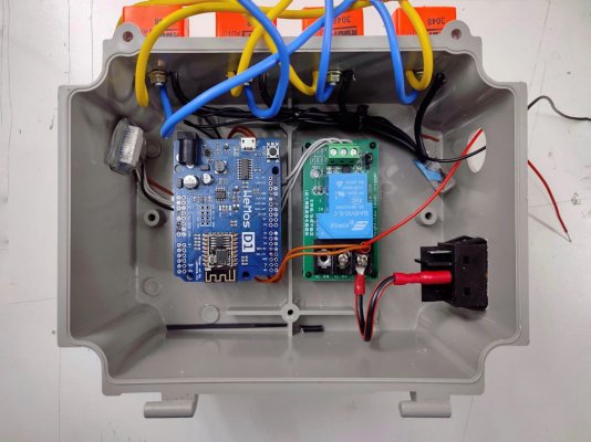
With the boards installed in the box, I added transparent heatshrink on the INA219 module.
But that's just an elaborate low voltage cutoff, I still wanted some way of visualizing data so onwards we go.
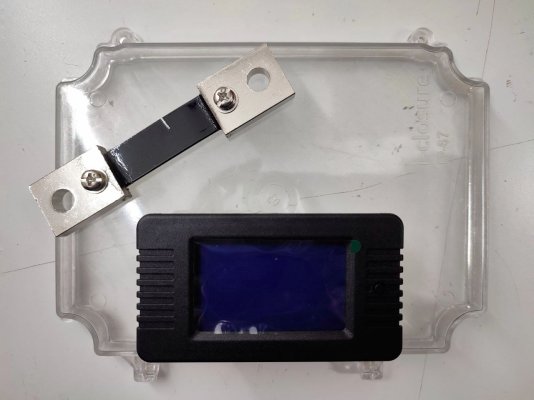
This is a Peacefair PZEM015 DC current meter, complete with a ridiculously overbuilt shunt for 100A from robu.in
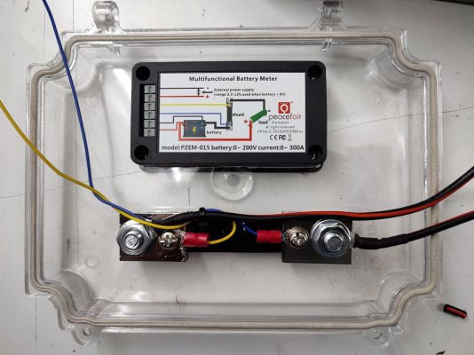
The meter is installed in the lid and the shunt is wired up.
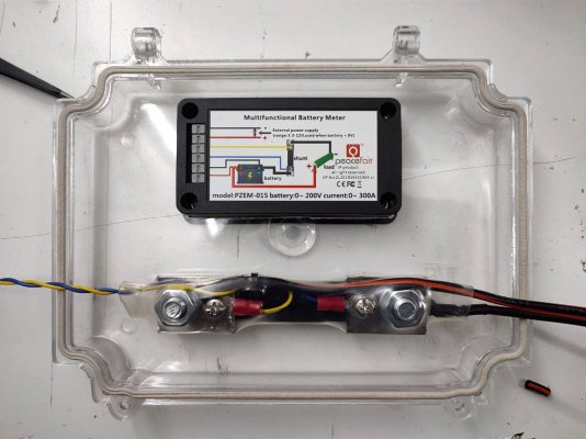
Transparent heatshrinking on the shunt.
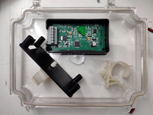
I found these clips/clamps on a decommissioned ATM last year and finally found a use for them, the shunt will be clipped on the back of the meter.
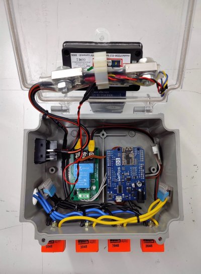
Here's everything almost wired up. I'm not using the highbeam on these bulbs, so I tied off those blue wires. The yellow wires are connected into a 5-way WAGO connector, which is then connected to the NC (normally closed) contact of the relay. The common contact of the relay goes to the switch. Both the Peacefair module and the ES8266/INA219 are connected to the common contact, so that they're not affected by the relay cutting off the bulbs.
This way, the bulbs are on when you turn on the switch, and turn off only when you either turn off the switch, or the ESP8266 modules triggers the relay when it detects a low voltage reading. So the relay is only energised (thus drawing power) when there's a low voltage cutoff in effect.
Hopefully this means I can leave this tester unattended until I get a notification from a Tasmota -> Telegram integration.
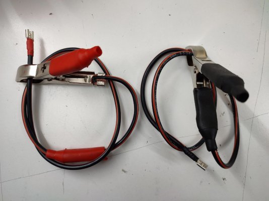
Some quick battery clamps I hammered together from quartzcomponents.com, all of the wiring is 4 sq mm.
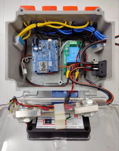
Another angle of the mostly completed battery tester. Now to try it out:
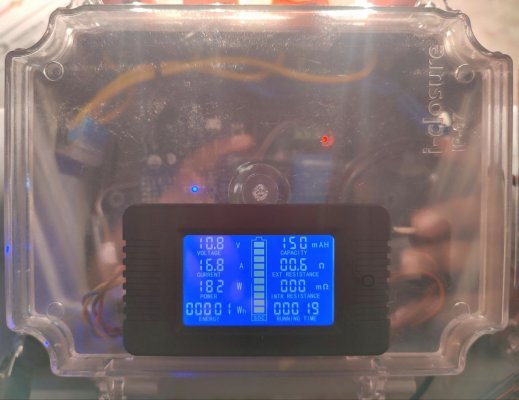
With three bulbs (2x 55w and 1x 90w), it's drawing 16.8 amps and voltage fell under 11V immediately, indicating a pretty much dead battery.
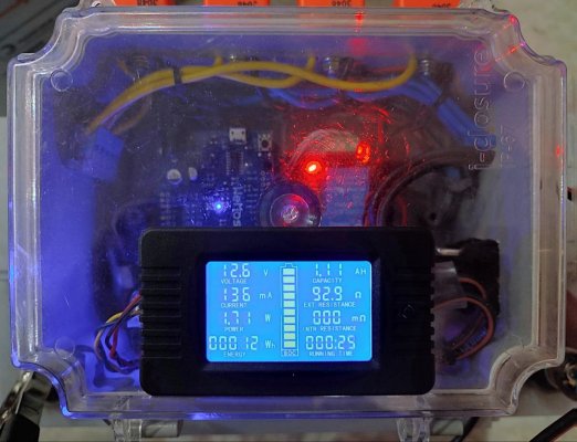
The low voltage cutoff kicked in at 10.5V and turned off the bulbs (by energizing the relay — there's two red leds illuminated instead of one)
Looking at the datasheet for this battery: https://amaronquanta.com/wp-content/uploads/2021/07/Quanta-100Ah.pdf

I should've seen 5 hours of run time at 17 amps down to 1.75 volts per cell (1.75 x 6 = 10.5V) which works out to be 5 x 17 = 85Ah capacity. Instead I got 1.11Ah (show in the display above).
So yeah, it's a dead battery. But at least now I know how dead it is. Now I'm off to try desuphation.
But first, here's what to type in the Tasmota web console for the low voltage cutoff:
then turn on the rule with:
Also to make sure the relay stays de-energized at every power on (so that the bulbs are always turned on):
More about Tasmota rules: https://tasmota.github.io/docs/Rules/
and Power On State: https://tasmota.github.io/docs/PowerOnState/
Starting off: a junction box, some H4 bulb holders and some headlight bulbs:

The box was around Rs 400 on Amazon and the bulb holders were Rs 80 each, bulbs were about the same.

I removed the rubber sleeve, drilled a 4.5mm hole from the rear side, put back the rubber sleeve on, and continued drilling from the socket side and ended up with a clean hole in the rubber sleeve this way.

Spacing out the holder and marking holes for drilling.

Holders installed.

Each wire got an individual hole and the fasteners are M4 with serrated nuts.

There is some crowding on the bulb side though, I should've staggered the holders a bit.

I needed to snip off bits from the bulbs to get them fit.

Next up is installing this rectangle switch in a round hole.
Link for the 30A switch: https://www.amazon.in/FIREWELD-Rocker-Welding-Machine-machines/dp/B08QZVM5D6

Which was done with the help of a rotary tool.

I wasn't able to clean up the hole because the switch got stuck during a test fitting. It looks alright though.
At this point, that's the most essential parts of the load tester. But I wanted some telemetry, so onwards we go.

That's a Wemos D1 R2 ESP8266 module running Tasmota Sensors, connected to an INA219 for voltage monitoring and a 30A relay that serves as a low voltage cut off.

The wiring is the same as the battery monitors, with the addition of 5V lines and GPIO12 going to the relay.

With the boards installed in the box, I added transparent heatshrink on the INA219 module.
But that's just an elaborate low voltage cutoff, I still wanted some way of visualizing data so onwards we go.

This is a Peacefair PZEM015 DC current meter, complete with a ridiculously overbuilt shunt for 100A from robu.in

The meter is installed in the lid and the shunt is wired up.

Transparent heatshrinking on the shunt.

I found these clips/clamps on a decommissioned ATM last year and finally found a use for them, the shunt will be clipped on the back of the meter.

Here's everything almost wired up. I'm not using the highbeam on these bulbs, so I tied off those blue wires. The yellow wires are connected into a 5-way WAGO connector, which is then connected to the NC (normally closed) contact of the relay. The common contact of the relay goes to the switch. Both the Peacefair module and the ES8266/INA219 are connected to the common contact, so that they're not affected by the relay cutting off the bulbs.
This way, the bulbs are on when you turn on the switch, and turn off only when you either turn off the switch, or the ESP8266 modules triggers the relay when it detects a low voltage reading. So the relay is only energised (thus drawing power) when there's a low voltage cutoff in effect.
Hopefully this means I can leave this tester unattended until I get a notification from a Tasmota -> Telegram integration.

Some quick battery clamps I hammered together from quartzcomponents.com, all of the wiring is 4 sq mm.

Another angle of the mostly completed battery tester. Now to try it out:

With three bulbs (2x 55w and 1x 90w), it's drawing 16.8 amps and voltage fell under 11V immediately, indicating a pretty much dead battery.

The low voltage cutoff kicked in at 10.5V and turned off the bulbs (by energizing the relay — there's two red leds illuminated instead of one)
Looking at the datasheet for this battery: https://amaronquanta.com/wp-content/uploads/2021/07/Quanta-100Ah.pdf

I should've seen 5 hours of run time at 17 amps down to 1.75 volts per cell (1.75 x 6 = 10.5V) which works out to be 5 x 17 = 85Ah capacity. Instead I got 1.11Ah (show in the display above).
So yeah, it's a dead battery. But at least now I know how dead it is. Now I'm off to try desuphation.
But first, here's what to type in the Tasmota web console for the low voltage cutoff:
Code:
rule1 on INA219#Voltage<10.5 do power1 0 endonthen turn on the rule with:
Code:
rule1 1Also to make sure the relay stays de-energized at every power on (so that the bulbs are always turned on):
Code:
poweronstate 1More about Tasmota rules: https://tasmota.github.io/docs/Rules/
and Power On State: https://tasmota.github.io/docs/PowerOnState/
Last edited:

